

In chemical recycling and thermal conversion, the commercial viability of a plastic pyrolysis plant is often decided before the material ever reaches the reactor. While substantial investment and attention naturally center on reactor design, catalyst selection, and oil condensation, seasoned plant operators understand an engineering reality: a pyrolysis reactor is only as dependable as the feedstock fed into it.
Feeding raw, unclassified, wet, or contaminated plastic waste into a continuous pyrolysis reactor triggers severe operational failures—including rapid catalyst poisoning, acidic reactor corrosion, pipe and condenser tar plugging, poor heat transfer, and out-of-spec pyrolysis oil. Achieving reliable, 24/7 continuous operation requires an engineered plastic pyrolysis feedstock preparation line.
Engineering Note: Energycle manufactures industrial mechanical recycling and material preparation systems—including shredders, granulators, friction washers, sink-float separation tanks, and high-speed dewatering machines. We do not manufacture pyrolysis reactors. Our role is engineering the front-end physical preparation lines that convert contaminated, mixed plastic waste into clean, dry, dimensionally uniform feedstock optimized for downstream thermal reactors.
The Pyrolysis Feedstock Preparation Process Flow
A properly designed pre-treatment system is modular. Depending on whether your raw material is clean post-industrial scrap or heavily soiled post-consumer packaging, the preparation line integrates five core stages to meet downstream reactor specifications:
- Mechanical & Density Sorting: Removing ferrous and non-ferrous metals, sand, and fundamentally incompatible polymers (primarily PVC and PET).
- Shredding & Secondary Granulation: Reducing bulky waste, bales, or rigid moldings into the precise particle size required by the reactor feed mechanism.
- Washing & Friction Cleaning (Selective): Scrubbing off organic soils, abrasive grit, and surface labels to reduce inorganic ash and protect downstream equipment.
- Mechanical Dewatering & Thermal Drying: Stripping surface moisture down to strict reactor entry limits (typically <1% to <3%).
- Bulk Density Optimization (Optional): Agglomerating or compacting fluffy film flakes or woven raffia to prevent feed hopper bridging and ensure steady extruder/screw intake.
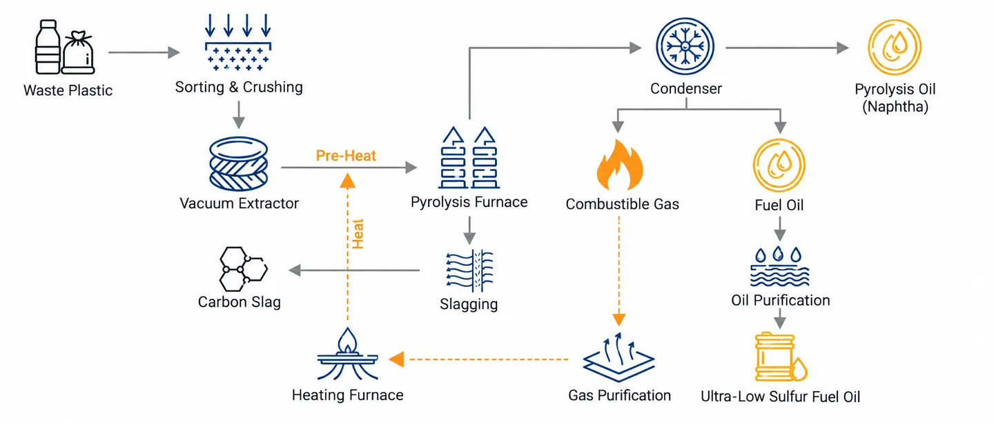
Within this thermal conversion circuit, the front-end mechanical pre-treatment line bridges raw waste and the reactor. The engineering flow below details the mechanical progression from mixed plastic into reactor-ready polyolefin feed:
Raw Mixed Plastic Waste (Post-Consumer Bales / Rigid Scrap / Film Waste)
  │
  ├──► [Upstream De-metaling] ──► Overband Magnetic Separator (Removes Fe Scrap)
  │
  ├──► [Primary Size Reduction] ─► Heavy-Duty Single/Twin-Shaft Shredder (50–100 mm)
  │
  ├──► [Polymer Sorting] ────────► Air Classification & Sink-Float Tank (Separates Polyolefins from PVC/PET)
  │
  ├──► [Secondary Granulation] ──► Wet/Dry Rotary Granulator (Down to 10–25 mm Flakes)
  │
  ├──► [Surface Cleaning] ───────► High-Speed Friction Washer (Dislodges Grit, Adhesives & Dirt)
  │
  ├──► [Mechanical Dewatering] ──► Centrifugal Dewatering Machine (Removes Free Water down to 2–3%)
  │
  ├──► [Thermal Moisture Trim] ──► Pneumatic Pipe Flash Dryer (Brings Core Moisture <1%)
  │
  ├──► [Density Conditioning] ──► (For Film/Foam only) Compactor / Agglomerator (Dense Granules)
  │
  ▼
Ready for Pyrolysis Reactor (Homogeneous, Dry, Chlorine-Controlled Polyolefin Feedstock)
Which Plastics Are Suitable for Pyrolysis? Controlling PVC & PET
Thermal pyrolysis relies on the scission of carbon-carbon polymer backbones in an oxygen-free environment. Not all commodity plastics yield desirable hydrocarbons under these conditions:
- Preferred Polyolefins (PP, HDPE, LDPE, LLDPE): Polyolefins are the gold standard for plastic-to-liquid (PtL) pyrolysis. Their chemical structure consists exclusively of carbon and hydrogen. Cracking produces high yields (typically 70% to 85% by weight) of paraffinic and olefinic synthetic crude oil, diesel-range hydrocarbons, and petrochemical naphtha feedstocks.
- Polystyrol (PS): PS undergoes clean thermal depolymerization, yielding a high fraction of aromatic styrene monomer and dimer oil with minimal char.
- Incompatible / Problematic Polymers (PVC, PET, Polyurethane): These resins must be strictly identified and rejected during front-end preparation.
Why PVC Content Must Be Under 0.1% (Chlorine Control)
Polyvinyl Chloride (PVC) contains approximately 56% chlorine by weight. In thermal conversion, PVC poses catastrophic operational and chemical hazards:
- Severe Acidic Corrosion: PVC begins dehydrochlorination at relatively low temperatures (250°C to 350°C), well before polyolefins undergo thermal cracking (400°C to 500°C). It releases large volumes of volatile hydrochloric acid gas (HCl), which attacks carbon steel and stainless reactor walls, condenser tubes, and seals.
- Downstream Catalyst Poisoning: Chlorinated hydrocarbons carried over into the liquid pyrolysis oil severely poison the expensive hydrotreating catalysts (such as Ni-Mo or Co-Mo) used in steam crackers or refineries. Most petrochemical off-takers demand chlorine levels below 10 to 50 ppm.
- Toxic Dioxin / Furan Precursors: Chlorine in thermal processes introduces regulatory risks regarding chlorinated dioxins in non-condensable off-gases.
Pre-treatment Solution: Upstream optical/NIR sorting can eject PVC containers and profiles. In mechanical washing lines, our Schwimm-Sink-Trenntanks utilize clean water (density = 1.0 g/cm³) to separate light polyolefins (PP and PE float, density 0.89–0.96 g/cm³) from heavy sinking contaminants (PVC sinks, density 1.35–1.45 g/cm³), protecting the pyrolysis line from chlorine contamination.
Why PET Must Be Minimized (Oxygen & Sublimation Risks)
Polyethylene Terephthalate (PET) contains roughly 33% oxygen. Unlike polyolefins, thermal cracking of PET produces virtually no liquid fuel. Instead, it yields carbon dioxide, carbon monoxide, heavy carbonaceous char, and large volumes of benzoic acid and terephthalic acid.
Terephthalic acid sublimes into the gas vapor stream and rapidly recrystallizes upon entering cooling condensers and pipe elbows. These solid acid crystals form stubborn crusts that choke condenser tubes, create dangerous overpressure conditions in the reactor, and contaminate downstream oil fractions. In mechanical pre-treatment, PET is effectively eliminated in the same sink-float stage (PET sinks at density ~1.38 g/cm³).
| Polymer Type | Dichte (g/cm³) | Suitability for Pyrolysis | Key Risk if Not Removed | Recommended Pre-treatment Stage |
|---|---|---|---|---|
| Polypropylen (PP) | 0.89 – 0.91 | Excellent (75–85% oil yield) | None (Target feed) | Retain in floating fraction |
| Polyethylene (HDPE / LDPE) | 0.91 – 0.96 | Excellent (70–80% oil yield) | High wax content if cracked at lower temperatures | Retain in floating fraction |
| Polystyrol (PS) | 1.04 – 1.06 | Good (Yields styrene monomer) | Sinks in pure water; requires specialized saline or optical separation if co-processed | Optical sorting or separate PS feed stream |
| Polyvinylchlorid (PVC) | 1.35 – 1.45 | Unacceptable (<0.1% max limit) | HCl gas corrosion, equipment destruction, catalyst poisoning (>10–50 ppm Cl in oil) | Optical sorting + Sink-Float Separation Tank |
| Polyethylenterephthalat (PET) | 1.34 – 1.40 | Unacceptable (Negligible oil yield) | Sublimation of terephthalic acid, condenser blocking, high char and gas yield | De-labeling + Optical sorting + Sink-Float Separation Tank |
Feedstock Particle Sizing: Matching the Reactor Type
Plastics are thermal insulators with low heat conductivity. In any thermal cracking unit, particle size dictates the heat transfer rate from the reactor medium to the core of the plastic particle. If particles are too large, the exterior decomposes into gas and char while the core remains uncracked, causing uneven residence time and high uncracked residues. However, over-grinding waste into ultra-fine dust wastes electrical power and generates excessive airborne fines.
The optimal particle geometry depends directly on the reactor’s feeding mechanism and heating method:
1. Continuous Extruder & Auger Feed Systems (10 mm to 25 mm)
Continuous commercial plants typically utilize twin-screw feeding extruders or heated plug augers to melt and pump plastic into the reactor while forming a dynamic vapor seal. These feed screws require uniform, free-flowing regrind between 10 mm and 25 mm. Oversize chunks create torque spikes and screw bridging, while irregular shapes impede smooth volumetric metering.
2. Fluidized Bed Pyrolysis Reactors (5 mm to 15 mm)
Fluidized bed reactors utilize hot circulating fluidizing sand or solid catalysts for rapid, high-temperature heat transfer. They demand narrow particle distributions, typically 5 mm to 15 mm. Larger chunks cannot be suspended in the bed, causing localized hot spots, defluidization of the sand bed, and premature shutdowns.
3. Rotary Kiln & Batch / Semi-Continuous Units (30 mm to 80 mm)
Heavy rotary kilns with internal flights tolerate coarser primary shred (30 mm to 80 mm). However, reducing the feed from 80 mm down to 25 mm significantly cuts batch heating cycle times, improves volumetric fill factor, and lowers energy consumption per ton of throughput.
To achieve high throughput and precise size distribution without knife overheating, Energycle configures a two-stage reduction layout: a low-speed, high-torque industrieller Kunststoffzerkleinerer for primary breakdown of bales, rigid drums, or purgings, followed by an industrial Kunststoffgranulator fitted with interchangeable classification screens.
Washing & Moisture Control: Centrifugal Dewatering vs. Thermal Drying
One of the most frequent questions from pyrolysis project developers is: “Does all plastic pyrolysis feedstock need to be washed and dried?” The answer is strictly governed by your raw material source and your reactor’s moisture tolerance.
When Is Washing Necessary?
- Clean Post-Industrial Off-cuts: Baled edge trim, injection sprues, blow molding flash, and clean warehouse stretch wrap require zero washing. Direct shredding, metal detection, and feeding save substantial capital and operating expenditure.
- Post-Consumer & Agricultural Waste: Packaging film, municipal rigid bottles, and agricultural mulch film carry high concentrations of sand, dirt, organic matter, and paper labels. Unwashed dirt acts as an abrasive that ruins feed screws and accumulates inside the reactor as inert ash. Unwashed paper fibers introduce organic oxygen, degrading oil quality. These streams require high-intensity friction washing and float-sink cleaning.
Why Moisture Control Is Critical
Water entering a pyrolysis reactor at 450°C flashes instantaneously into steam (expanding by over 1,600 times its liquid volume). This creates serious operational problems:
- Parasitic Heat Consumption: Water requires an enormous latent heat of vaporization (2,260 kJ/kg). Heating water inside the reactor wastes expensive electricity, natural gas, or pyrolysis syngas.
- Condenser Overload & Pressure Surges: Steam displaces condensable hydrocarbon vapors, overloads condensing systems, and creates unpredictable reactor pressure swings.
- Stable Water-Oil Emulsions: Water condensing alongside light and medium oils forms tight emulsions that complicate oil/water separation tanks and require chemical demulsifiers.
Most commercial continuous reactors set strict moisture ceilings between 0.5% and 3.0%. Meeting this target requires selecting the right mechanical and thermal drying steps:
| Drying Technology | Operating Mechanism | Typical Moisture Output | Energieaufnahme | Best Applied To |
|---|---|---|---|---|
| Zentrifugalentwässerungsmaschine | High-speed rotor (1,200–1,500 RPM) generating dynamic G-force against a perforated basket | 2.0% – 3.0% (Rigid Flakes) 5.0% – 8.0% (Thin Film) |
Very low (Mechanical only, ~0.02–0.04 kWh/kg) | Primary dewatering after wash tanks for rigid HDPE/PP flakes |
| Pneumatic Pipe Flash Dryer | Hot air flash drying column with cyclone discharge | < 0.5% – 1.0% | Moderate to high (Requires thermal heat: gas/electric/syngas) | Secondary moisture trim for rigid flakes or thin film meeting strict <1% reactor specs |
| Mechanical Squeeze Dryer | Variable-pitch heavy-duty compression screw with perforated barrel | 3.0% – 5.0% (Film only) | Low to moderate (Mechanical compression + friction heat) | Primary dewatering for washed agricultural and post-consumer LDPE/PP film |
For rigid polyolefin flake lines, an Energycle Zentrifugalentwässerungsmaschine provides the most cost-effective first-stage dewatering. Where downstream catalytic or fluidized reactors require moisture under 1%, the centrifugal unit is paired with a secondary pneumatic thermal pipe dryer, recovering waste heat from the pyrolysis process to finalize moisture removal.
Is Plastic Densification Necessary Before Pyrolysis?
A widespread assumption in new pyrolysis ventures is that all plastic feed must be re-pelletized or agglomerated before entering the reactor. In reality, pelletizing requires high electrical energy (typically 0.25 to 0.45 kWh/kg), high capital equipment expenditure, and thermal shearing that can prematurely degrade polymers. Whether densification is necessary depends entirely on the physical form of the scrap:
Rigid Plastics (Flakes): No Densification Needed
Rigid HDPE bottle regrind, PP bucket flakes, and PS regrind have a natural bulk density of 0.35 to 0.50 kg/L. This material flows freely under gravity, settles evenly into feeding hoppers, and is readily handled by standard variable-speed feed screws. Re-pelletizing or compacting rigid flakes adds capital cost without operational benefit.
Flexible Films and Woven Bags: Densification Often Crucial
Lightweight film flakes, shredded shopping bags, and PP raffia have an extremely low bulk density, often below 0.03 to 0.08 kg/L. Feeding fluffy film directly into a pyrolysis reactor causes severe operational headaches:
- Hopper Bridging and Feed Starvation: Low-density film flakes interlock, creating arches across feeding bins that choke feed screws and starve the reactor.
- Severe Throughput Derating: Because feed screws are volumetric devices, feeding material at 0.05 kg/L yields only a fraction of the mass throughput achieved with dense flakes.
- Air / Nitrogen Entrainment: Fluffy film carries large volumes of interstitial air into the feeding extruder, introducing unwanted oxygen and nitrogen into the anaerobic reactor.
Die Lösung: Instead of costly melting and re-pelletizing, post-consumer film is processed through an agglomerator or cutter-compactor. High-speed frictional knives briefly generate surface heat that softens the film, collapsing its structure into dense, free-flowing granules with a bulk density of 0.30 to 0.45 kg/L. For an in-depth mechanical comparison, review our guide on granulators vs. agglomerators.
Pre-treatment Line Configurations: Tailored to Your Feedstock
To avoid over-capitalizing on equipment your plant does not need, Energycle designs pre-treatment lines customized to specific feedstock streams:
Configuration A: Clean Post-Industrial Polyolefins (Dry Mechanical Route)
Feedstock: Factory scrap, rejected moldings, injection purgings, clean film rolls.
Konfiguration:
- Incline feed conveyor with tunnel metal detector.
- Single-shaft shredder with hydraulic pusher ram for primary breakdown.
- Overband magnetic separator to catch tramp steel.
- Secondary rotary granulator with 16 mm classification screen.
- Buffer storage silo with screw discharger directly to the reactor feeder.
Key Advantage: Low CAPEX, minimal energy consumption, zero water consumption or drying required.
Configuration B: Post-Consumer Mixed Rigid Packaging (Wet Wash & Density Route)
Feedstock: Baled mixed curbside bottles, containers, and rigid packaging.
Konfiguration:
- Bale breaker / Debaler and sorting belt for large contaminant removal.
- Heavy-duty shredder for bottle opening and coarse sizing (40–60 mm).
- Overband cross-belt magnet for ferrous removal.
- High-speed rotary granulator with water injection (wet crushing to 14 mm).
- High-speed friction washer to dislodge labels, dirt, and organic residues.
- Sink-float separation tank: PP/PE float to the top; PVC, PET, glass, and metals sink for discharge.
- Centrifugal dewatering machine to mechanically reduce flake moisture to 2.5%.
- Optional thermal flash drying duct for lines requiring <1.0% moisture.
Key Advantage: Highly consistent polyolefin purity, rigorous chlorine/PVC removal, clean dry flakes for automated reactor feeding.
Configuration C: Agricultural & Post-Consumer Film (Wash & Densify Route)
Feedstock: Agricultural greenhouse film, silage wrap, municipal plastic bags.
Konfiguration:
- Film shredder with anti-wrap rotor design.
- Heavy particle separator and rock trap to protect knives from soil and gravel.
- Friction washer and dynamic sink-float separation tank.
- Mechanical dewatering screw press to squeeze bulk water out of film webs.
- Thermal hot-air pipe drying system.
- High-speed film agglomerator / compactor to produce dense, free-flowing granules (0.35 kg/L).
Key Advantage: Converts high-soil, low-bulk-density film waste into dense, high-flow granules that feed reliably without screw stalling or air entrainment.
Engineering Checklist: Defining Your Feedstock Specification
When selecting and sizing equipment for a plastic pyrolysis pre-treatment line, define these six project parameters before ordering:
- Polymer Composition & Stream Source: Ratio of PE/PP vs. contaminants (PVC, PET, nylon, moisture, and inert dirt).
- Target Reactor Particle Size: Minimum and maximum particle envelope (e.g., 10–25 mm for augers, 5–15 mm for fluidized beds).
- Maximum Allowable Moisture (%): Define whether your reactor requires <3% (achievable mechanically) or <1% (requiring thermal drying).
- Maximum Allowable Chlorine (ppm Cl): Target chlorine ceiling for downstream pyrolysis oil off-takers (dictates sorting sensitivity).
- Target Hourly Throughput: Operational capacity in kg/h or tons/day, accounting for scrap yield losses during sorting and washing.
- Site Utilities & Energy Integration: Availability of industrial water supply, wastewater treatment, and potential waste heat recovery from the pyrolysis flare or reactor flue gas.
Conclusion: Engineer the Front End for Reactor Reliability
In plastic pyrolysis, reactor uptime, catalyst longevity, and oil marketability depend directly on feedstock discipline. Investing in proper front-end mechanical preparation—removing PVC and PET, shredding to an exact dimensional range, washing out abrasive soils, and controlling moisture—is the single most reliable strategy to eliminate costly reactor shutdowns and maximize return on investment.
If you are developing a chemical recycling or plastic pyrolysis project, Kontakt Energycle. Share your expected raw plastic stream, throughput targets, and downstream reactor feeding specifications. Our mechanical engineering team will help design, size, and supply a modular feedstock preparation line that delivers clean, reliable feedstock from day one.