

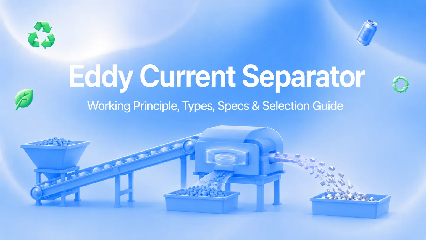
An eddy current separator (ECS) recovers conductive non-ferrous metals — including aluminum, copper, brass and zinc — from mixed material streams by electromagnetic repulsion. This guide explains the main rotor configurations, the operating variables that affect separation, realistic fine-particle limits and the information needed to specify an ECS for MSW, ASR, IBA, WEEE, glass, plastic and other recycling applications.
What Is an Eddy Current Separator?
An eddy current separator is an electromagnetic sorting machine that separates non-ferrous metals from non-metallic materials on a conveyor belt. The core mechanism: a high-speed magnetic rotor spinning inside a non-metallic shell drum generates rapidly alternating magnetic fields. When conductive metals pass through these fields, electric currents (eddy currents) are induced inside the metal pieces, creating their own magnetic fields that oppose the rotor’s field. The resulting repulsive force launches non-ferrous metals forward off the belt, while non-conductive materials (plastic, glass, wood, paper) simply fall off the belt end by gravity.
The separation force depends on a material’s conductivity-to-density ratio. Aluminum (high conductivity, low density) separates most easily. Copper and brass (high conductivity but higher density) require stronger fields or slower belt speeds. Stainless steel and lead respond poorly to eddy current separation due to low conductivity or very high density.
How Does an Eddy Current Separator Work?
The working principle follows Faraday’s law of electromagnetic induction and Lenz’s law. Four stages determine the final separation:
Step 1: Prepare and Spread the Feed
Ferrous metal is removed upstream, and screening narrows the particle-size range. A vibratory feeder or spreading conveyor then presents a thin, even layer. Particle-on-particle collisions and buried metal pieces reduce the difference between the metal and non-metal trajectories, so stable monolayer feeding matters more than a headline throughput figure.
Step 2: Expose Material to the Rotor Field
At the conveyor discharge, a high-speed magnetic rotor turns inside a non-magnetic shell. Alternating north and south poles create a rapidly changing magnetic field at the belt surface. The appropriate rotor speed is application-specific; many industrial systems operate within roughly 2,000–5,000 RPM, but the best setting must be established by testing the actual feed.
Step 3: Induce Eddy Currents
When a conductive non-ferrous particle enters the changing field, circulating electrical currents are induced inside it. The particle creates an opposing magnetic field and experiences a repulsive force. Conductivity, density, particle size, shape and orientation all affect the resulting throw.
Step 4: Split the Trajectories
Eddy-current repulsion, belt momentum and gravity combine to give conductive particles a different flight path from non-conductive material. An adjustable splitter divides the two streams. Commissioning therefore requires coordinated adjustment of rotor speed, belt speed, feed depth and splitter position rather than changing one setting in isolation.
For a focused explanation of the rotor, conveyor and separation physics, read How an Eddy Current Separator Works in Metal Recycling.
Types of Eddy Current Separators
ECS selection involves two separate design questions: rotor geometry (concentric or eccentric) and magnetic frequency/intensity (pole count, magnet arrangement and rotor speed). “High-frequency” is not automatically a third geometry; it can be engineered into different rotor configurations. See our detailed eccentric vs. concentric rotor comparison for the trade-offs.
Concentric Rotor ECS
The magnetic rotor is centered inside the shell, creating a symmetrical field around the pulley. Standard concentric systems are commonly used for stable medium and coarse fractions in MSW, C&D, glass, wood and general scrap applications. High-intensity concentric designs can also be configured for smaller particles, so rotor geometry alone does not define the lower particle-size limit.
Eccentric Rotor ECS
The magnetic rotor is offset toward the discharge zone, concentrating the useful field where separation occurs and allowing attracted ferrous carryover to leave a diminishing field. Eccentric designs are often selected for fine, light or lower-conductivity particles and difficult fractions such as IBA, WEEE and granulated plastics.
High-Frequency Fine-Fraction ECS
Fine-fraction machines use application-specific pole arrangements, magnetic intensity and rotor speed to increase field changes at the belt surface. Specialized systems can recover suitable conductive particles in the low-millimeter range, but the practical cut point depends on particle mass, shape, moisture, feed depth and preparation. Energycle’s high-recovery ECS for fine aluminum uses a high-frequency concentric rotor; other fine-fraction duties may favor an eccentric design.
Eddy Current Separator Configuration Comparison
| Configuration | Field characteristic | Typical best fit | Selection note |
|---|---|---|---|
| Standard concentric | Symmetrical field | Medium/coarse, steady feed | Prioritize stable feeding, belt width and throughput |
| High-intensity eccentric | Focused discharge-zone field | Fine or difficult fractions | Confirm recovery and purity with a representative sample |
| High-frequency fine-fraction | Rapid pole changes; geometry varies | Screened fines, small WEEE, IBA and plastic granulate | Do not specify by particle size alone; test shape, mass and conductivity |
Important: recovery percentage is not a fixed property of a rotor type. It must be reported together with feed composition, particle-size distribution, moisture, throughput, product purity and the sampling method used during the test.
Key Operating Parameters
ECS performance is the result of several interacting variables. Record the baseline, change one parameter at a time and confirm both metal recovery and product purity with repeatable sampling.
1. Rotor Speed and Pole Configuration
A faster rotor increases the rate of magnetic-field change, but it does not guarantee a longer metal throw. If field exposure becomes too brief, displacement can plateau or decline. Use the manufacturer’s tested operating window and optimize it against a representative feed sample.
2. Belt Speed
Belt speed affects burden depth, dwell time and the natural trajectory of every particle. A faster belt may spread the feed more thinly while also shortening field exposure and flattening the trajectory difference. There is no universal belt-speed setting; it must be commissioned together with rotor speed and splitter position.
3. Splitter Position
The adjustable divider balances recovery against purity. Moving it to capture a wider metal trajectory can increase recovery while admitting more non-metallic material. Set the cut point against the downstream buyer or process specification, not appearance alone.
4. Feed Layer and Particle-Size Distribution
A thin, uniform layer exposes conductive particles to the field and reduces collisions. Screen broad feeds into narrower fractions when possible; a setting suitable for large cans is unlikely to be optimal for small wire or foil fragments. Wet, sticky or dusty material may require drying, deagglomeration or specialized feeding before separation.
5. Ferrous Pre-Removal
Ferrous metal is attracted to the magnetic rotor and can heat, damage the belt or shell, obstruct non-ferrous separation and cause downtime. Install an appropriate magnetic separator upstream and define an acceptable residual-ferrous limit during material testing and commissioning.
Material Separation Performance
Not all non-ferrous metals separate equally. The governing factor is the conductivity-to-density ratio (σ/ρ) — higher ratios produce stronger separation forces. Here is how common materials rank:
| Material | Conductivity (MS/m) | Density (kg/m³) | Relative σ/ρ index* | ECS response |
|---|---|---|---|---|
| Aluminum | 37.7 | 2,700 | 14.0 | Excellent — primary target metal |
| Magnesium | 22.6 | 1,740 | 13.0 | Excellent |
| Copper | 59.6 | 8,960 | 6.7 | Good — needs slower belt or higher RPM |
| Brass | 15.9 | 8,500 | 1.9 | Moderate — larger pieces only |
| Zinc | 16.6 | 7,130 | 2.3 | Moderate |
| Lead | 4.8 | 11,340 | 0.4 | Poor — density too high |
| Stainless Steel | 1.4 | 7,900 | 0.2 | Very poor — use sensor-based sorting |
*Illustrative index calculated as conductivity divided by density in g/cm³. Values represent typical pure-material data near room temperature; alloy composition, particle shape and size can materially change real separation behavior.
nn
The relative values explain why aluminum is generally easier to eject than dense, lower-conductivity metals. Stainless steel and mixed alloys may require sensor-based sorting, density separation or another downstream process.
How to Maximize Aluminum Recovery
Aluminum responds strongly to eddy-current separation, but recovery still depends on feed preparation and commissioning. Treat the following as a test plan rather than guaranteed performance:
| Feed fraction | Indicative particle size | Configuration to evaluate | Commissioning focus |
|---|---|---|---|
| Whole cans / UBC | >50 mm | Standard concentric | Throughput, stable feed and splitter position |
| Coarse shred | 20–50 mm | Concentric or eccentric | Particle shape, burden depth and product purity |
| Medium fraction | 10–20 mm | High-intensity configuration | Narrow screening and coordinated speed adjustment |
| Fine fraction | About 3–10 mm | Application-specific high-frequency ECS | Dry, even feed; sample testing; repeatable mass balance |
Three practices have the greatest practical impact:
- Screen before separation. Split a broad feed into fractions and commission each fraction against its own recovery and purity target.
- Use a documented mass balance. Sample feed, metal product and reject streams over the same time period. Record mass, metal content, throughput and settings so later adjustments can be compared.
- Maintain a stable monolayer. Do not trade feed depth for headline throughput if buried particles and collisions reduce saleable metal recovery.
For example, a 5 t/h line with 2% aluminum in the feed processes 100 kg/h of aluminum. Raising measured recovery from 80% to 93% captures an additional 13 kg/h. At one 8-hour shift for 250 operating days, that equals about 26 tonnes per year before accounting for availability, product purity and metal price. Use your own operating hours and assay data in the ROI model.
Specifications Reference
The values below summarize Energycle’s current fine-aluminum ECS family. They are reference ranges for one product series, not universal limits or guaranteed throughput. Final sizing depends on bulk density, particle-size distribution, conductive-metal loading, moisture, target purity and plant layout.
| Selection item | Reference range | Why it changes |
|---|---|---|
| Effective belt width | 330–1,200 mm | Feed volume, burden depth and available space |
| Rotor speed | Up to 3,000–4,000 RPM, model dependent | Rotor diameter, pole configuration and target fraction |
| Belt speed | 0–2 m/s adjustable | Dwell time, material trajectory and throughput |
| Drive power | 0.75–2.2 kW in this series | Belt width and mechanical configuration |
| Feed system | Application-specific | Material flow, moisture, bridging and monolayer control |
Review the high-recovery eddy current separator for fine aluminum for current model data, then confirm the final configuration with a representative material test.
Industry Applications
Eddy current separators are used wherever a prepared material stream contains valuable or unwanted conductive non-ferrous metal. The correct setup varies by application:
Municipal Solid Waste (MSW) Recycling
MRFs use ECS after ferrous removal to recover aluminum cans and other non-ferrous packaging. Plant capacity alone is not enough for sizing; the ECS must be matched to the screened fraction, burden depth and peak feed condition. See our MSW sorting machine lineup.
Auto Shredder Residue (ASR)
ASR contains aluminum, copper, brass and zinc among plastics, rubber and glass. Screening the material into coarse and fine fractions before one or more ECS stages usually produces a more controllable separation than treating the full size range with one setting.
Incineration Bottom Ash (IBA)
Processed IBA can contain recoverable aluminum and other non-ferrous particles across a wide size range. Fine-fraction recovery requires tight screening, moisture control and a rotor/feed configuration validated against the actual ash.
Electronic Waste (WEEE)
After controlled shredding and ferrous removal, ECS can recover bulk aluminum and copper-rich fractions from WEEE. Sensor sorting, density separation or manual quality control may still be needed to separate mixed metals and circuit-board material.
PET and Glass Purification
ECS can remove aluminum closures, foil and other conductive contaminants from prepared PET flakes or glass cullet. The achievable residual-metal level depends on particle liberation, screening, feed stability and the sampling method; verify it against the downstream buyer or process specification.
Construction & Demolition Waste
After size reduction, screening and ferrous removal, ECS can recover aluminum profiles, copper wire, brass fittings and other non-ferrous metals from mixed aggregate, wood and plastics.
Where ECS Fits in a Recycling Line
An eddy current separator normally operates as one stage in a prepared sorting line:
- Size reduction — a shredder or crusher liberates materials when required
- Screening — a trommel or vibrating screen creates controlled size fractions
- Ferrous removal — an overband, drum or pulley magnet removes steel and iron
- Stable feeding — a feeder spreads material evenly across the ECS belt
- Eddy current separation — conductive non-ferrous metal follows a different trajectory
- Downstream upgrading — sensor, density or manual sorting meets the final product specification
Facilities with a broad particle-size distribution may use separate coarse- and fine-fraction ECS stages. The benefit of a second stage should be demonstrated by a mass-balance test rather than assumed from a generic recovery percentage.
5-Step Selection Framework
Use this framework before requesting a quotation. For a deeper commercial comparison of price drivers, suppliers and used equipment, see the Eddy Current Separator Buyer’s Guide.
Step 1: Characterize the Feed
Provide the material source, non-ferrous metal types, particle-size distribution, bulk density, moisture, temperature, ferrous content and representative photos or samples. State whether the target is metal recovery, product purification or both.
Step 2: Define Capacity and Feed Conditions
Report average and peak feed rates together with bulk density and operating hours. Belt width must maintain a controllable layer at peak conditions, so capacity should be confirmed with the real material rather than selected from width alone.
Step 3: Set Measurable Acceptance Criteria
Define recovery, product purity, residual metal in reject, throughput and availability targets. Specify the sampling method and test duration so supplier results can be compared on the same basis.
Step 4: Confirm the Complete Supply Scope
Verify screening, ferrous pre-removal, feeder, ECS, splitter, discharge chutes, controls, guarding, dust management, platforms and interfaces with upstream and downstream equipment. A separator cannot compensate for poor feed preparation.
Step 5: Compare Total Project Economics
Model saleable metal recovered per year, product purity penalties, power, wear parts, labor, planned downtime, freight, installation and commissioning. Run low/base/high metal-price scenarios and use the tested recovery result; avoid a payback promise based only on nominal machine capacity.
Maintenance and Troubleshooting
Use the machine manual and actual operating conditions to set maintenance intervals. Abrasive glass, ash, residual ferrous metal and high operating hours can shorten belt, shell and bearing life.
| Frequency | Task | What to record |
|---|---|---|
| Each shift / daily | Inspect feed, belt tracking, splitter and discharge | Build-up, abnormal noise, temperature and product quality |
| Per manufacturer schedule | Check belt tension, bearings and lubrication | Alignment, vibration, grease condition and operating hours |
| Condition-based | Inspect belt and non-magnetic shell wear | Wear location, thickness and residual-ferrous incidents |
| After feed or product changes | Repeat separation sampling | Throughput, recovery, purity and machine settings |
| Planned shutdown | Inspect rotor, drives, guards and electrical controls | Corrective work, replaced parts and next inspection date |
Common diagnostic paths:
- Low recovery: confirm feed composition, liberation, screening and monolayer distribution before changing rotor speed.
- Metal in reject: sample the loss by size and metal type, then adjust rotor speed, belt speed and splitter one variable at a time.
- Non-metal in the metal product: inspect collisions, burden depth and splitter position; verify that the target purity is realistic for the feed.
- Belt or shell damage: stop and check residual ferrous metal, belt tracking, trapped material and wear limits.
- Excessive vibration or heat: stop the unit and inspect rotor balance, bearings, drives and foreign material according to the lockout procedure.
Getting Started with Energycle
Energycle supplies configurable eddy current separation equipment and line-integration support. Start with our fine-aluminum ECS product page, then send the engineering team the information needed to select and test a configuration:
- material source, composition, particle-size distribution and moisture
- average and peak feed rate, bulk density and operating hours
- target metal recovery, product purity and downstream acceptance limits
- available layout, power, controls, guarding and discharge requirements
- a representative sample for separation testing when practical
Contact our engineering team for a project-specific configuration, material-test plan and quotation.
Frequently Asked Questions
How does an eddy current separator work?
A high-speed magnetic rotor creates a rapidly changing field at the conveyor discharge. Conductive non-ferrous particles develop eddy currents and an opposing magnetic field, so they follow a different trajectory from non-conductive material. Rotor speed, belt speed, feed depth and splitter position are commissioned together.
What metals can an eddy current separator recover?
ECS equipment can recover conductive non-ferrous metals such as aluminum, copper, brass, zinc and magnesium. Actual recovery varies with conductivity, density, particle size, shape, liberation, feed depth and machine settings, so performance should be confirmed by sampling.
What is the difference between concentric and eccentric eddy current separators?
A concentric rotor is centered inside the shell and produces a symmetrical field. An eccentric rotor is offset toward the discharge zone and concentrates the useful field there. Concentric designs are common for stable medium and coarse fractions; eccentric designs are often selected for difficult fines. High-frequency configurations can use different rotor geometries.
What particle size can an eddy current separator process?
Standard machines commonly process screened medium and coarse fractions, while specialized high-frequency systems can recover suitable particles in the low-millimeter range. There is no universal lower limit: conductivity, density, shape, moisture, feed depth and liberation determine whether a 1–3 mm particle can be separated reliably.
How much does an eddy current separator cost?
Price depends on belt width, rotor geometry, pole configuration, magnetic intensity, feeder and splitter design, controls, guarding, chutes, material testing, freight and commissioning. Compare quotations against the same feed data, acceptance criteria and supply scope instead of using a generic price range.
Why is ferrous removal needed before an eddy current separator?
Ferrous metal is attracted to the rotor and can heat, damage the belt or shell, obstruct non-ferrous separation and cause downtime. Use an upstream drum, pulley or overband magnet and verify the residual-ferrous level during commissioning.
Can an eddy current separator recover copper?
Yes. Copper is highly conductive but much denser than aluminum, so its throw can be shorter. Screen the feed, maintain a thin layer and optimize the rotor, belt and splitter settings against the copper particle size and product-purity target.
What maintenance does an eddy current separator require?
Routine work includes inspecting feed distribution, belt tracking, splitter position, bearings, drives, the non-magnetic shell and residual ferrous contamination. Belt, shell and bearing replacement should be condition-based and follow the manufacturer manual because wear varies greatly by material and operating hours.
Related Resources
- High-Recovery Eddy Current Separator for Fine Aluminum
- How an Eddy Current Separator Works
- Eccentric vs. Concentric Eddy Current Separator Rotors
- Eddy Current Separator Buyer’s Guide
- Suspended Self-Discharging Magnetic Separator
- Sorting Machinery for Plastic Recycling
- MSW Sorting Machines
- Hard Drive Shredder Selection Guide
